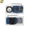
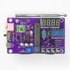
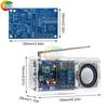
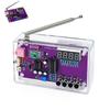
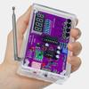
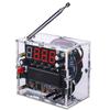
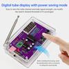
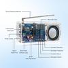
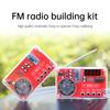
Quantity : 1
High-concerned chemical : none
Package : SOP
is_d : Yes
Dissipation Power : 3-5W
Supply Voltage : 5V
Type : Module
Brand Name : DIY NOW
Origin : Mainland China
Condition : New
Features
1. Full 87.5-108MHz band coverage with high sensitivity and strong anti-interference for stable signal reception
2. AXS2031 chip delivers 3-5W mono output with low-voltage distortion-free, smooth audio quality
3. 3.3V buck-boost module with 2.5-5.5V wide input voltage, Type-C/battery power supply selectable
4. Adjustable antenna design enhances signal reception, significantly improving sensitivity and stability
5. Clear soldering instructions suitable for DIY enthusiasts, boosting hands-on skills and sense of accomplishment
Parameter
Main control chip: STC8G1K08 microcontroller; FM receiver module uses RDA5807M, covering 87.5~108MHz frequency range for global coverage. Features high sensitivity, low noise, and strong anti-interference capabilities. Amplifier section employs AXS2031 digital amplifier chip (not TDA2822) for simple circuitry, high output power, and distortion-free performance down to 2.5V. The voltage regulation section employs a 3.3V buck-boost module. It maintains a stable 3.3V supply for the microcontroller and LED display even when the input voltage ranges from 2.5V to 5.5V. This contrasts with the AMS1117 regulator chip, where the microcontroller fails to operate normally and the LED display malfunctions when the voltage drops below 3V.
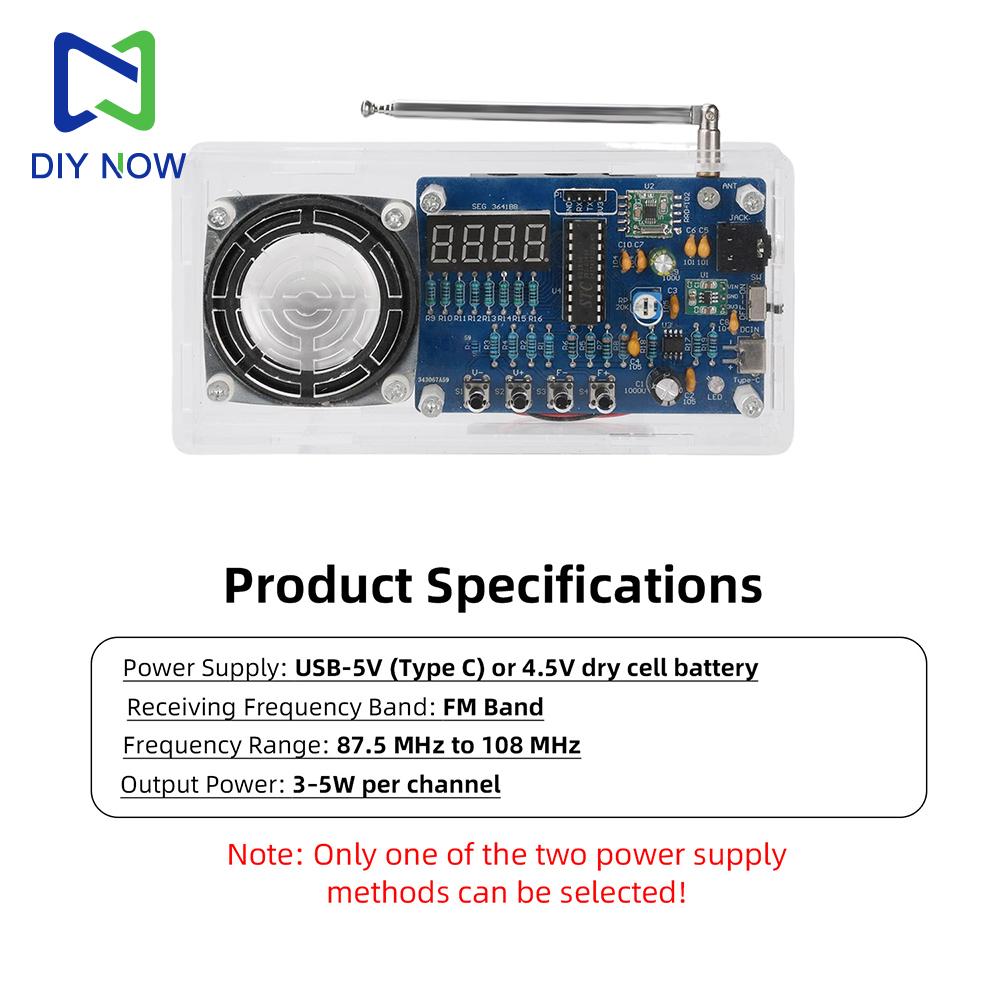
Product Specifications
Power Supply: USB-5V (Type C) or 4.5V dry cell battery
Reception Band: FM Band
Frequency Range: 87.5MHz~108MHz
Output Power: Mono 3~5W
Note: Only one power supply method can be used at a time!
Product Description
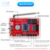
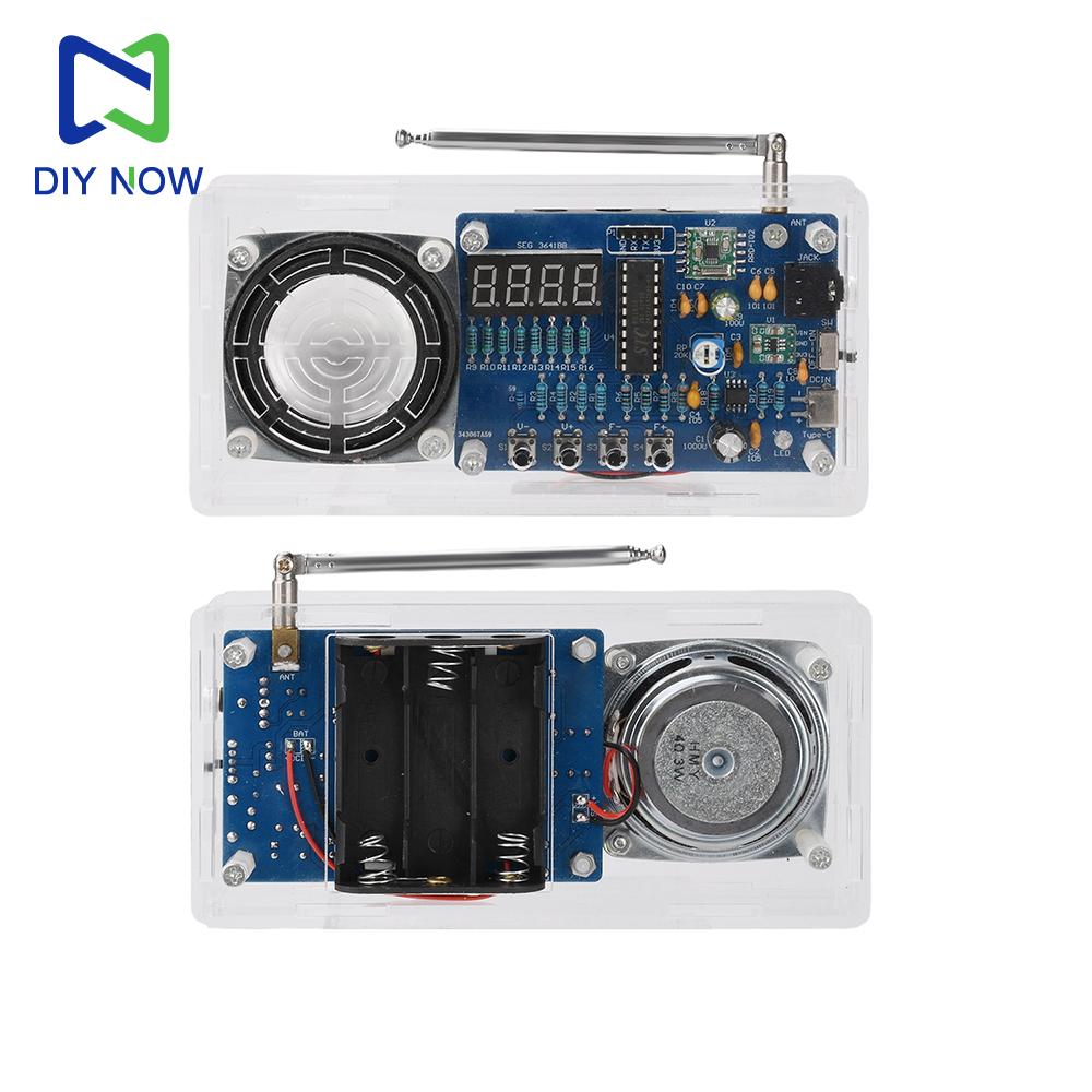
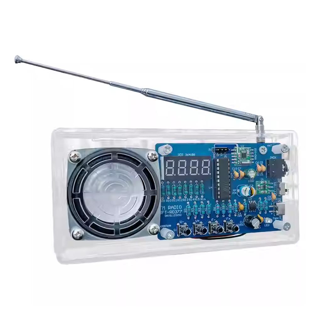
30cm Omni-Directional Antenna: We selected a 30cm omnidirectional antenna for signal reception. It can be rotated freely to adjust FM signal reception, significantly enhancing sensitivity for optimal reception.
3.3V Buck-Boost Module: The voltage regulation section employs a 3.3V buck-boost module. It stably outputs 3.3V when the input voltage is between 2.5V and 5V. Even when the voltage drops as low as 2.5V, it still outputs 3.3V, ensuring normal circuit operation. In contrast, the AMS1117 used by other manufacturers is not a boost converter. At voltages as low as 2.5V, the LED display fails to function properly, and the entire circuit operates abnormally. Anti-Distortion Amplifier Chip: The amplifier section employs the AXS2031 anti-distortion digital amplifier chip. operating within a 2.5–5.5V range. It delivers 3–5W of high-fidelity output at full load with 99% efficiency, producing smooth, non-harsh sound. Even at 2.5V, it maintains distortion-free performance, offering significantly superior audio quality compared to the TDA2822.
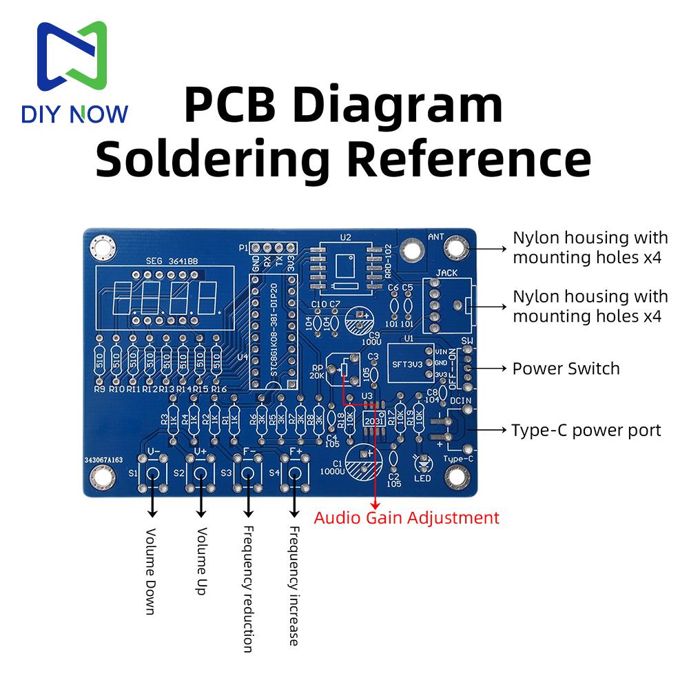
Soldering Instructions:
Before soldering, cross-reference the component list to ensure no parts are missing. Test transistors, capacitors, resistors, and other critical components with a multimeter for functionality. During soldering, prioritize thin surface-mount components and modules. Use either a soldering iron or a hot air gun with solder paste for rework. Elevate the PCB using a support frame, then insert components of similar height according to their pin numbers. To prevent components from falling during flipping, secure them to the PCB edge using adhesive tape. Flip the PCB with component leads facing upward. Trim excess lead length with needle-nose pliers, leaving approximately 1mm. Proceed with rapid soldering, following the principle of soldering from shortest to tallest components.
When installing the omnidirectional antenna, position its flat base flush against the soldered PCB back. Secure with M3 screws, adjust vertical alignment, and reinforce with solder joints. Finally, solder the leads to the speaker and battery compartment, then secure them to the PCB with double-sided tape according to their positions. Screw the male and female copper pillars onto the PCB, and conclude by assembling the enclosure.
Package include
Radio Kit*1
label:yes
Power: 10 W





 No-delivery refund